Reverse engineering an EV charger
We decided to look into one of the most prevalent chargers on Norwegian roads

Written by:


TL;DR
This blog post walks through our efforts reverse engineering the Zaptec Pro charger, an electric vehicle charger found in many parking lots and apartment buildings around Norway.
The post shows how we went about testing the device, including some of our trials and errors during the process. By analyzing the device’s firmware, and compiling a custom bootloader, we were able to root the device and dig into how it works.
Although we found that security appears to have been considered at multiple steps along the way in developing the Zaptec Pro charger, the blog post also presents some potential improvement areas.
Introduction
Electric vehicles have become quite common over the past few years. Here in Norway, they make up over half of all new car sales. The chargers that support EVs have effectively become critical infrastructure that we rely on for everyday life. At the same time, the publicly available information about how they work is limited.
Out of curiosity we decided to purchase the Zaptec Pro. This model was intended for larger, networked installations like parking lots and apartment buildings. The Zaptec Pro was among the most prevalent chargers on Norwegian roads at the time this post was written.
Device overview
The charger is a surprisingly powerful device. It runs a full-fledged Debian-based operating system with Wi-Fi, 4G LTE, Bluetooth, and power-line (PLC) network connectivity. It wouldn’t be too far off to think of it as a Raspberry Pi on steroids, with some 230V relays.
As an end user, Zaptec is probably just the logo you see on the black box you plug your car into. Behind the scenes however, Zaptec has a whole cloud ecosystem designed to switch those relays on and off, as well as bill you for electricity consumption.
To use a public charger a customer will normally have to download an app. These tend to be released by parking garage companies and charging network operators. A customer will enter their payment details in the app, and select a charger to use. At this point the app will make a request up to the cloud, and an integration between the app’s backend and Zaptec is used to start a new charging session.
Zaptec uses Azure IoT Hub to communicate with and control their devices. More on how this works is discussed below.
Teardown
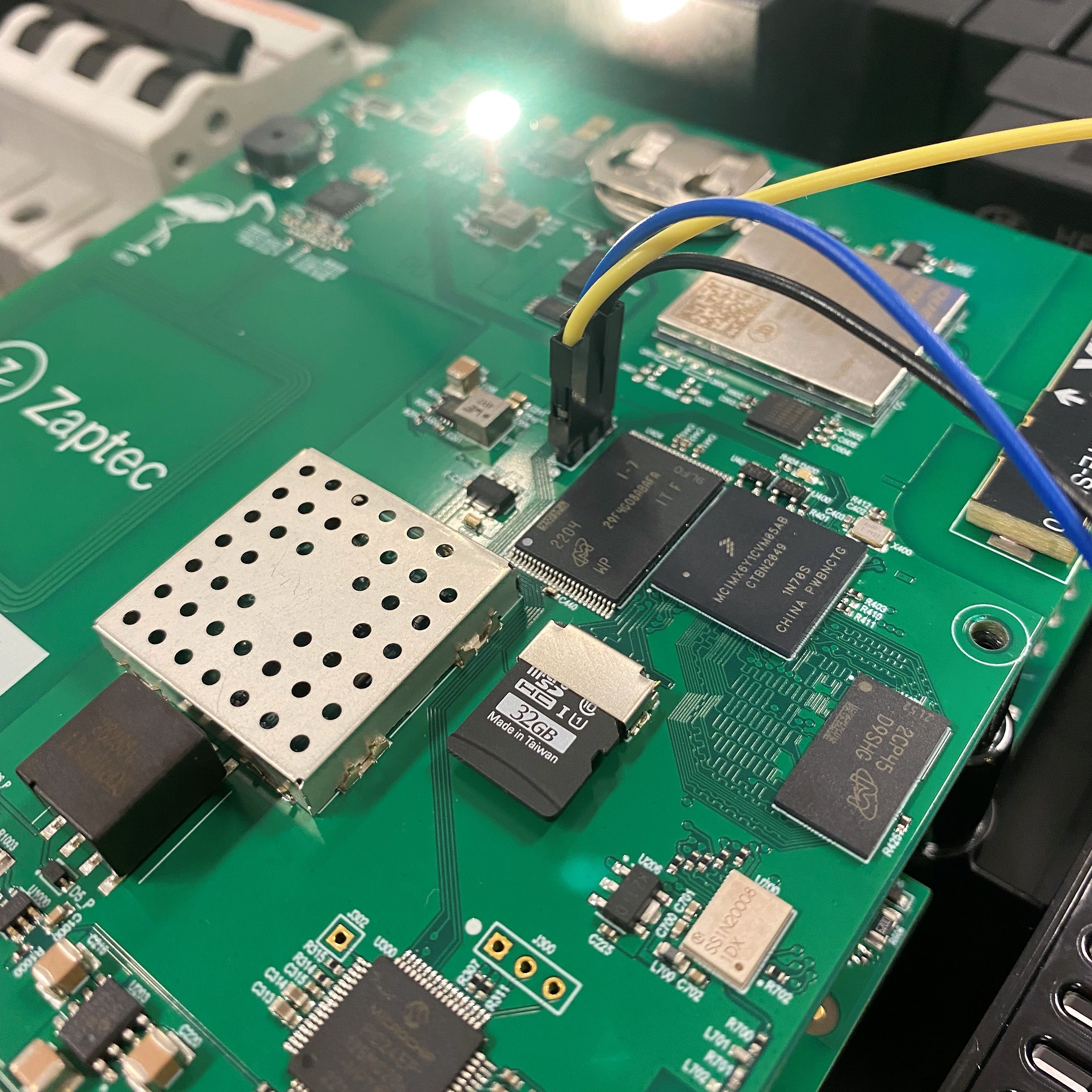
The charger has two PCBs, stacked on top of one another and linked via a 40-pin connector. The bottom PCB contains most of the power related components, while the upper PCB houses the “smart” components.
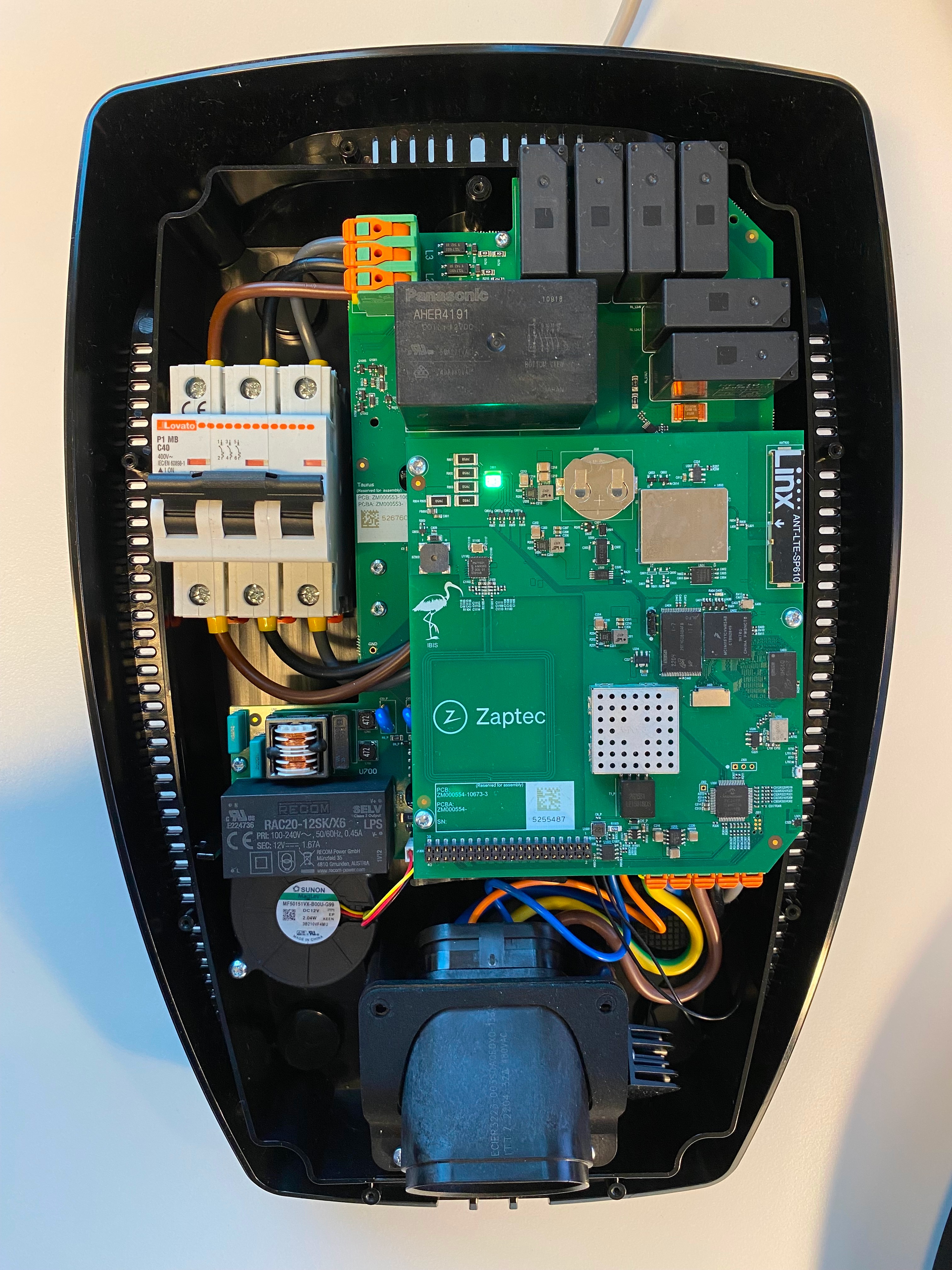
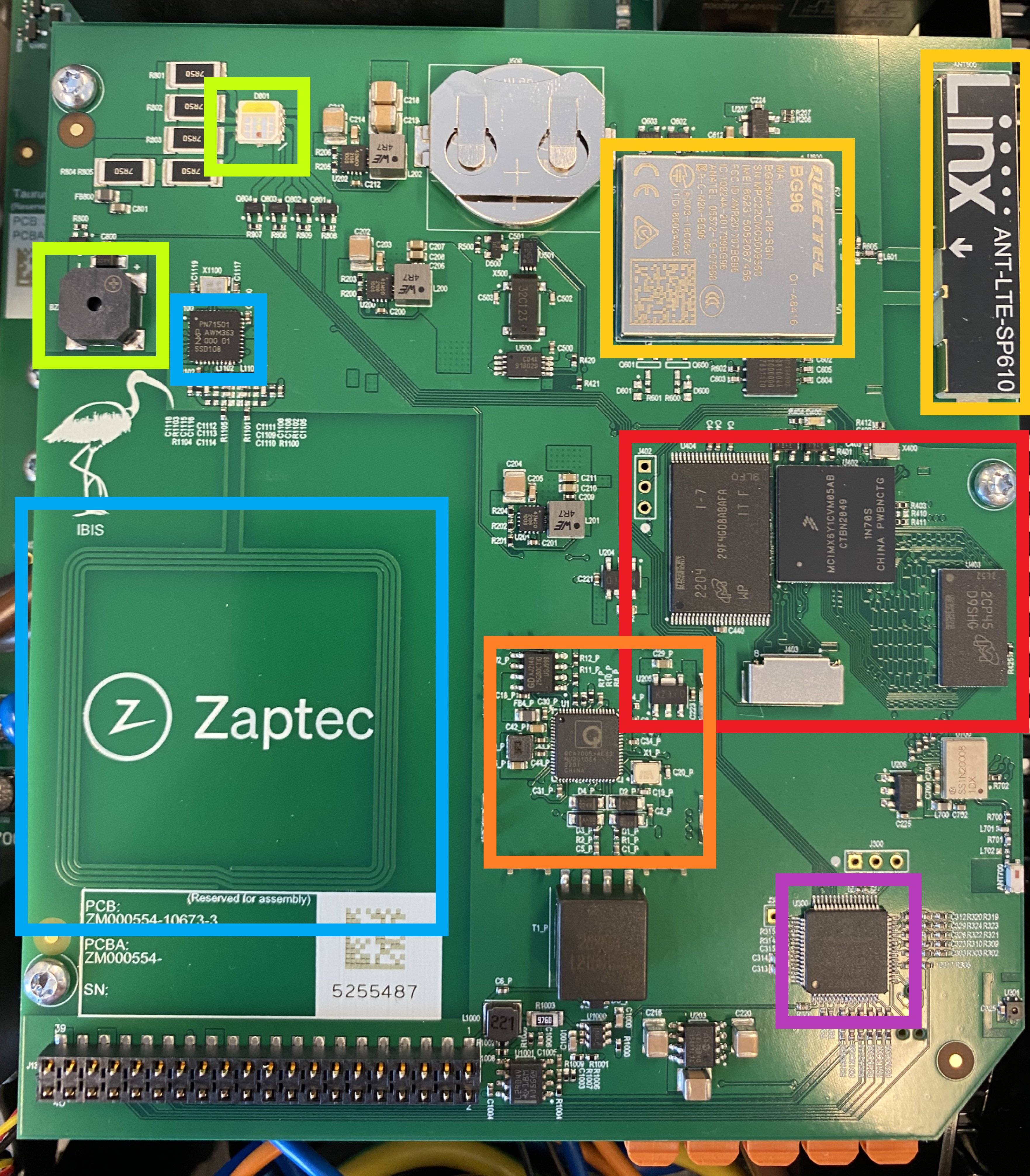
Taking a deeper look at the upper PCB, there are a few different components of interest:
- In green there’s the piezo buzzer and RGB indicator LED
- In blue there’s the RFID components
- Yellow is the 4G modem and antenna
- Orange is a QCA7005 Qualcomm chipset, used for network communication over power lines (PLC)
- Purple is a PIC24E microcontroller
- And in red from left right we have a 512 MB NAND flash memory chip, an ARM Cortex-A7 based microcontroller, and 512 MB of RAM
Debug interfaces
We had previously learned that the device was running Linux by connecting it to a Wi-Fi network and running a port scan. It had a SSH listener on port 22.
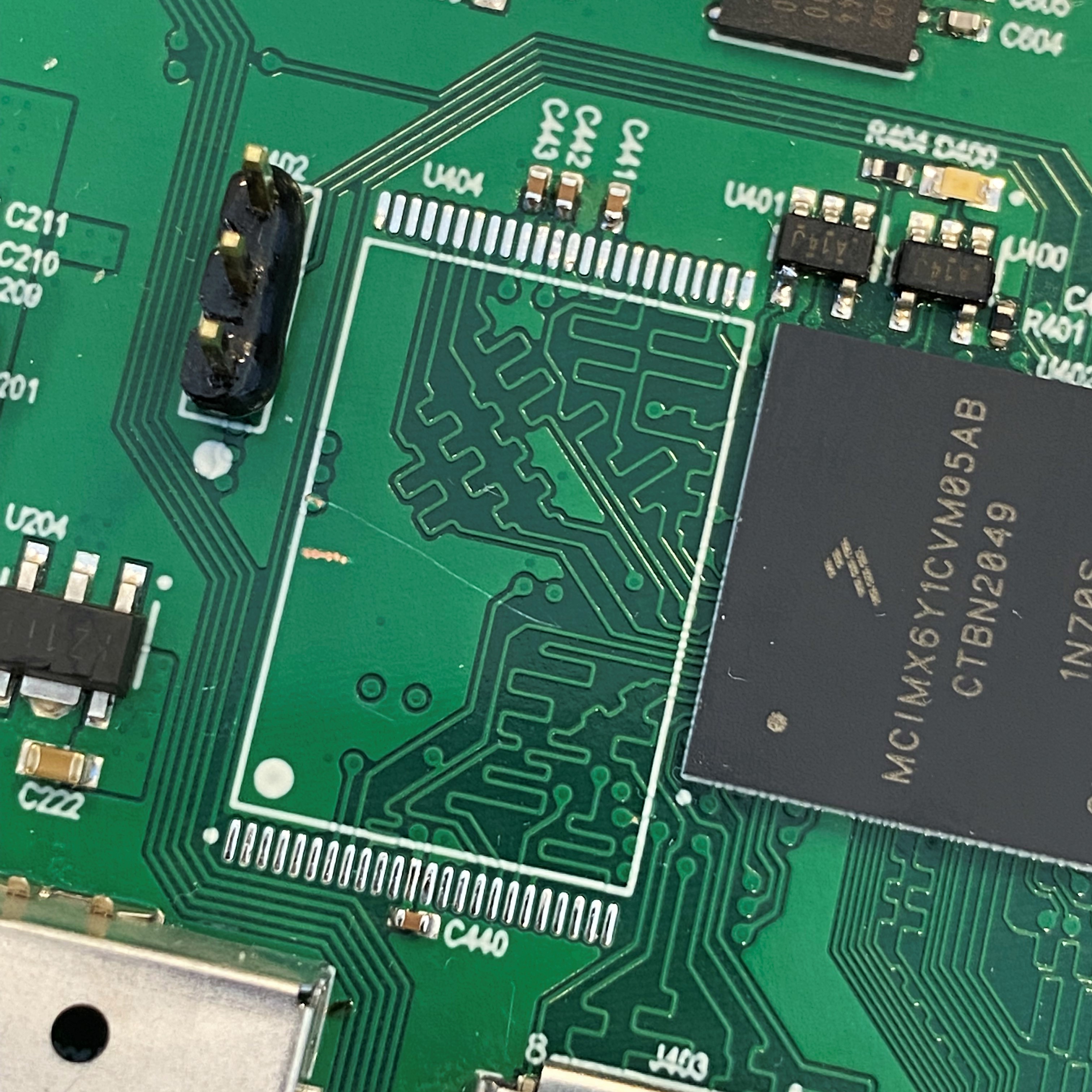
Basic brute-force password attacks didn’t work, so it was time to start looking around for debug interfaces on the PCB. The board had a fairly clean layout, and components were grouped into a few different sections. The most likely chip on the board to run Linux was the ARM processor. It was also next to flash storage and RAM chips, which seemed logical enough.
Since it was an ARM processor, we were hoping to see JTAG/SWD interfaces, and/or UART serial ports. The JTAG/SWD ports, if left enabled, should theoretically allow us to dump firmware and modify running code. The processor physically has all these pins, and can be found by looking at the datasheet. However, soldering to an in-circuit BGA was out of the question. So, we’re more or less at the mercy of what the designer’s exposed on the PCB. Though it’s not hard to notice an unpopulated 3-pin header to the left of the NAND flash.
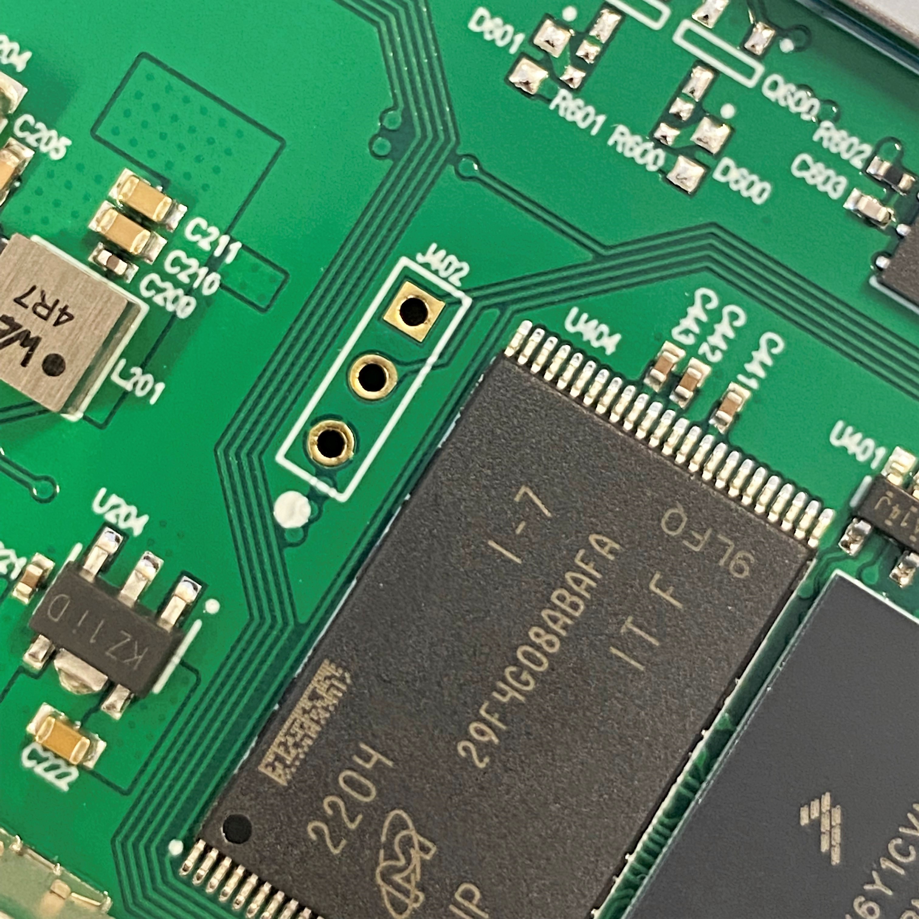
The header had three pins, one being ground, so it was probably:
- Nothing (disabled in production firmware)
- ARM’s Serial Wire Debug (SWD)
- UART
We soldered a header on and hooked up logic analyzer to the pins, and discovered a UART serial interface.
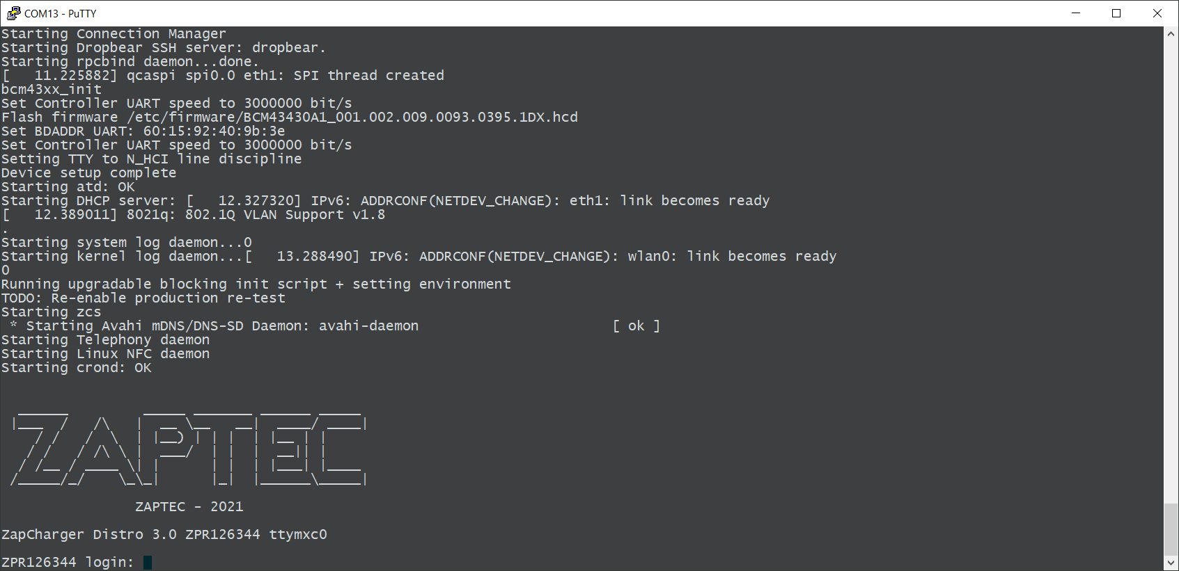
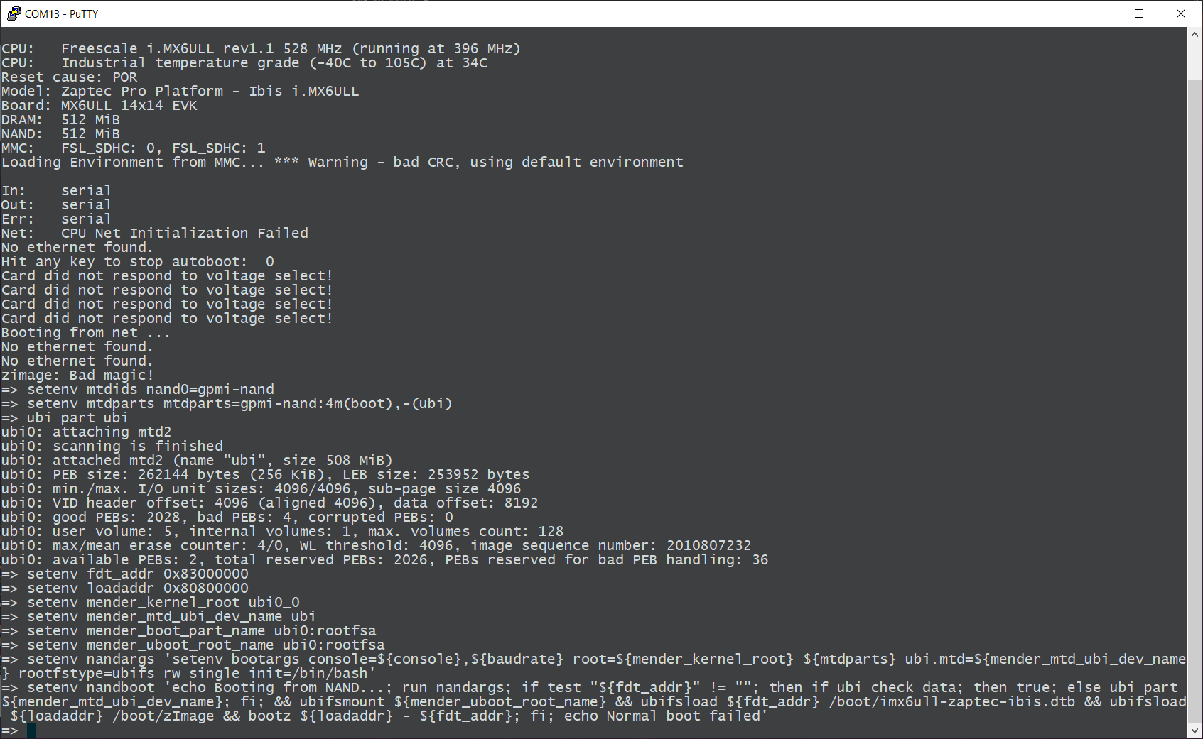
The console log provided useful information about the device, but unfortunately didn’t give us a shell. The bootloader had also been locked down and didn’t allow for interrupting the boot process, which prevented us from playing around in the U-Boot environment.
It was at this point we realized that little silver rectangle below the ARM processor was just about the right size to be a microSD card slot.
We put a SD card in the slot then reboot the charger. It didn’t boot. Either we made a brick, or the charger was trying to use the SD card as a boot device and we had nothing for it to boot. Removing the SD card and booting again validated our suspicions.
Investigating the boot process
We tried flashing the SD card with various images for development boards based on the same processor, with varying success. A few images managed to start but inevitably would hang in U-Boot before loading the Linux kernel.
This issue was ultimately down to the fact that there were hardware differences between the development board and the Zaptec PCB. This resulted in the images being incompatible. Zaptec likely used different ram, or connected the various components to different pins.
The way U-Boot and Linux know about the hardware configuration for a device is through a devicetree. This is essentially a file that describes hardware like RAM and flash storage, so that the OS knows how to interact with them. Normally, a designer will sit with board schematics to create a devicetree. Since we didn’t have access to Zaptec’s schematics we were left with finding another solution.
Dumping the NAND flash
Access to a device’s firmware is always nice to have. Not only would it provide further information about how the device worked, but if we got access to the Zaptec devicetree, it could allow us to compile our own compatible bootloader or OS.
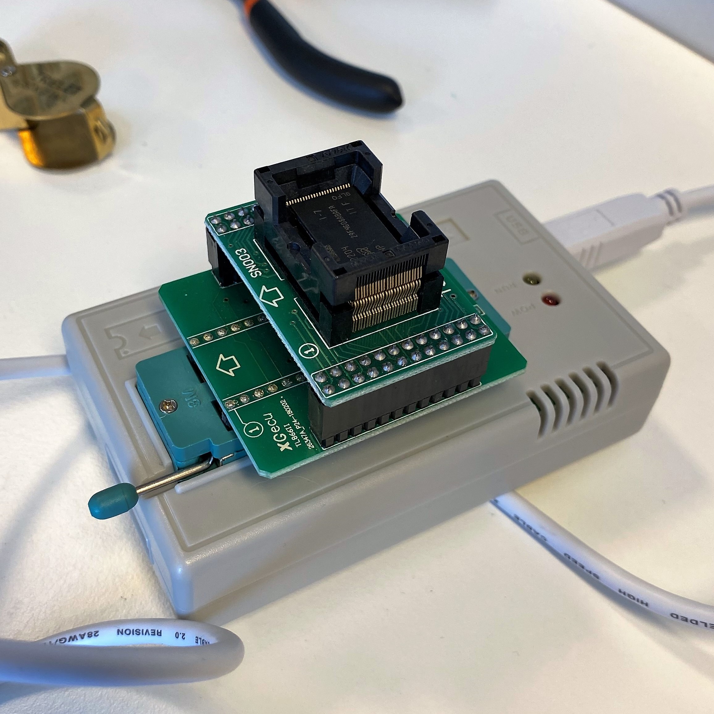
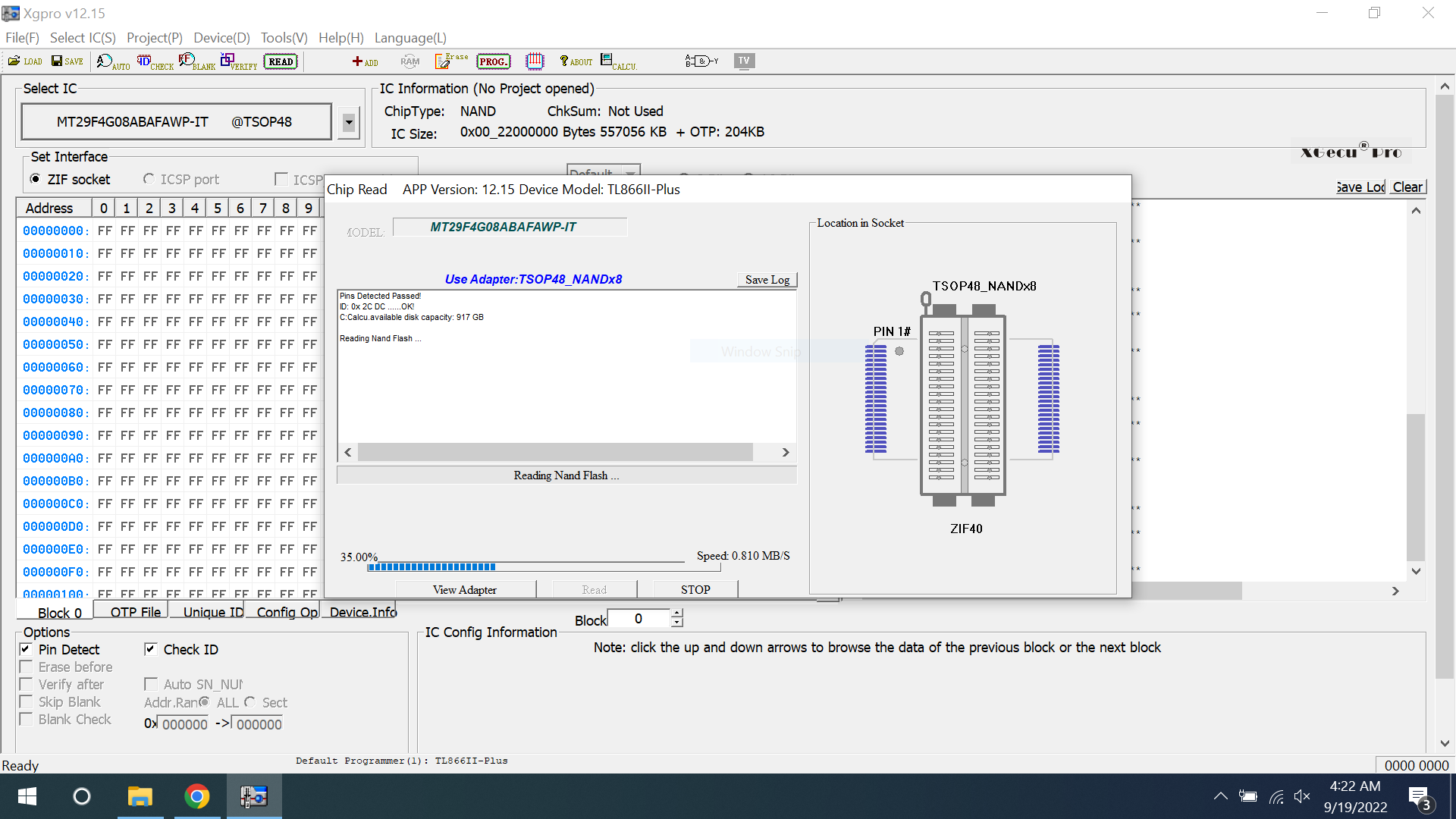
It wasn’t the cleanest job in the world, but we were able to successfully desolder the TSOP48 NAND chip and dump its contents using a TL866II Plus programmer.
Firmware analysis
The binary file produced by the programmer is an exact byte-for-byte copy of the NAND flash. This presents some challenges, as the partitions we want to analyze are mixed in with other data such as error correction bits and space reserved for wear leveling. This is known as out-of-band (OOB) data and is introduced by the NAND controller integrated into the ARM processor.
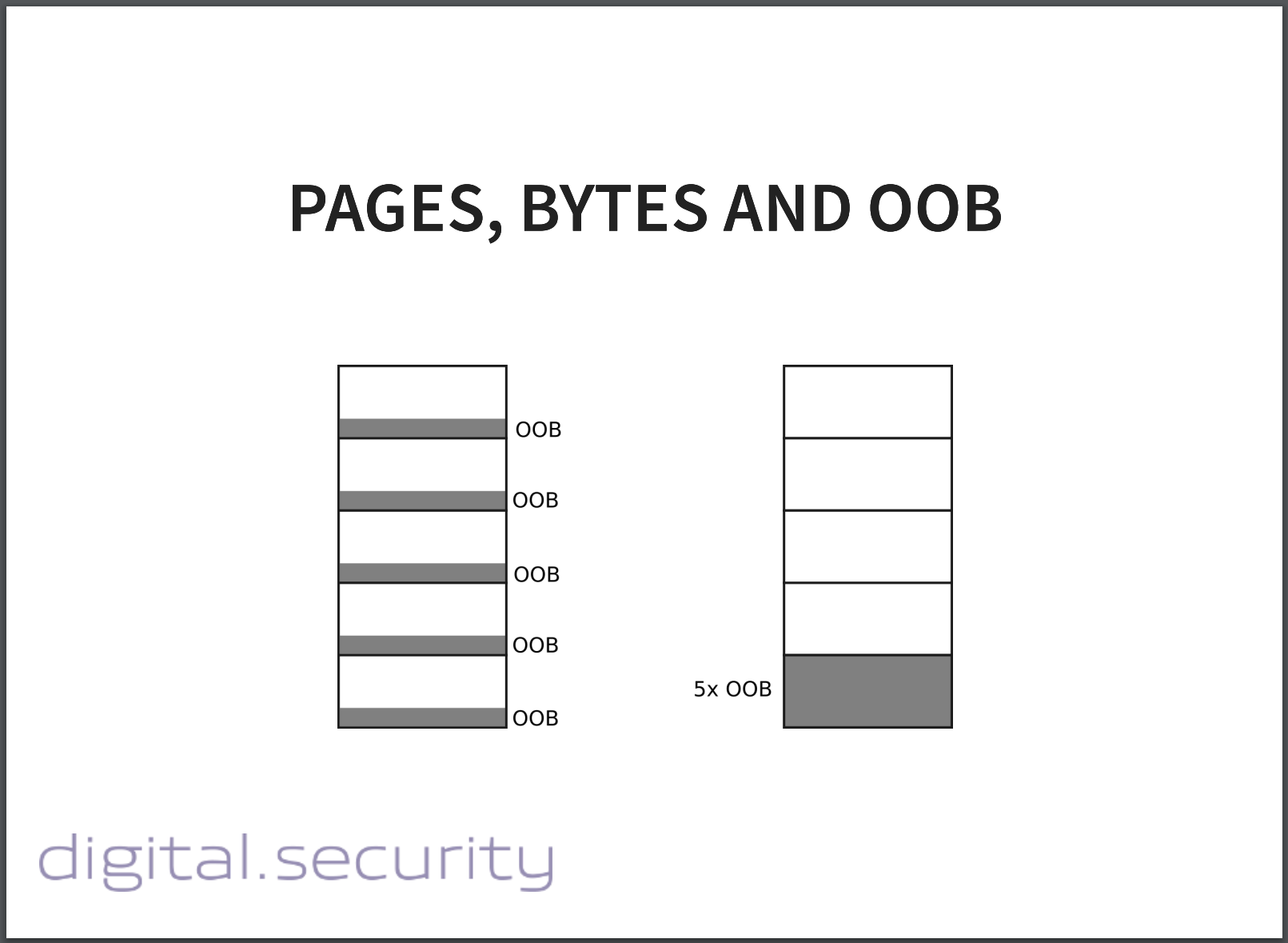
Damien Cauquil held a presentation at HITB Amsterdam in 2019 that went into detail about how this process works on I.MX based processors. Lucky for us, he released a tool that removes the OOB data. It produces a binary file similar to what U-Boot or Linux would see when interacting with the NAND flash.
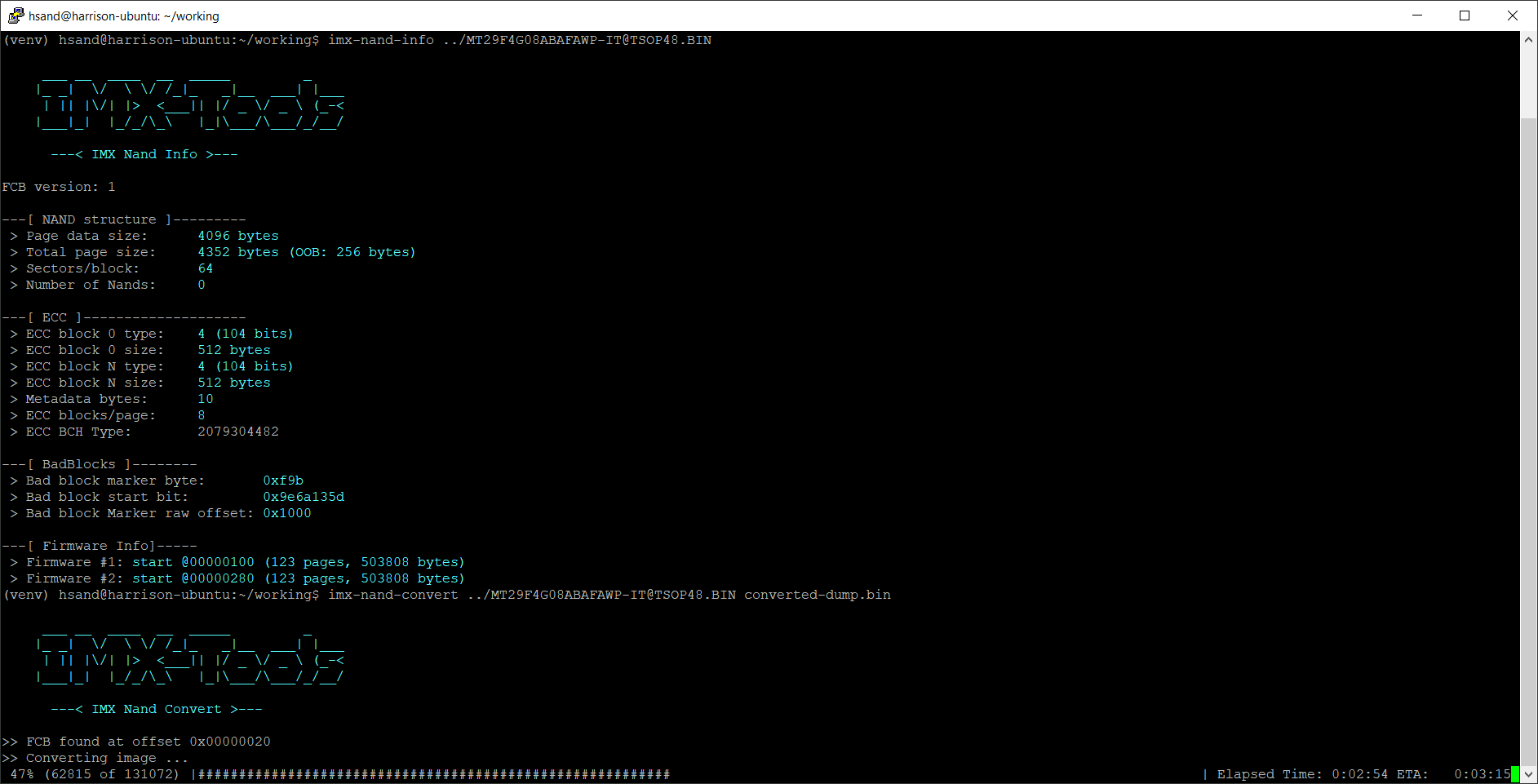
After poking around in the firmware for a while, we were able to carve out Zaptec’s devicetree binary from the boot partition.
Compiling a custom bootloader
We considered building Linux to boot from the SD card, but eventually decided to just compile U-Boot. If we resoldered the NAND flash, and had the ability to enter a U-Boot environment, we could control the boot arguments passed to the Linux kernel. This would allow us to enter single user mode, which essentially just drops you into a root shell without prompting for a password.
We included the devicetree binary as part of the U-Boot build process, and flashed the bootloader to an SD card. Once in our custom U-Boot environment we set some environment variables that told U-Boot to boot from the NAND flash and enter single user mode.
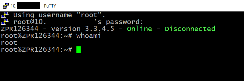
Once in single user mode we set a new root password, and rebooted without the SD card. Now we could connect with SSH over WiFi using our new root password!
How things work
Now with root access to a running device, we wanted to investigate a few different aspects of how the charger worked.
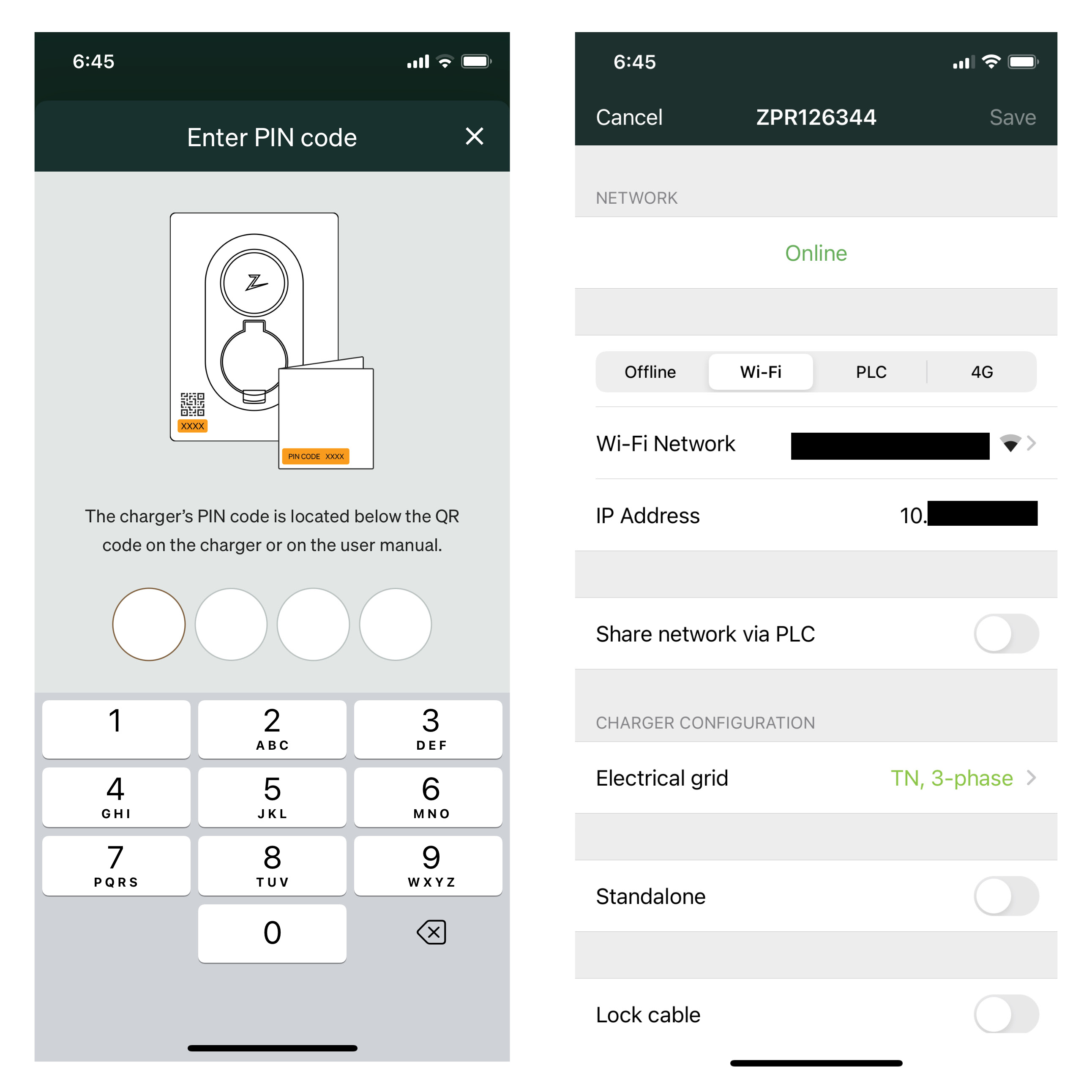
The Bluetooth PIN code
The device comes set from the factory with a four-digit PIN code. It’s printed on the box and can’t be changed. It is used to manage a few settings, like how the charger connects to the internet.
Two questions we wanted to answer were:
- How was the PIN code generated? Many IoT devices generate security codes from easily guessable identifiers, like a serial number or MAC address. If this was true in this case, maybe we could manage arbitrary devices.
- What can you do with access to a devices PIN code? Can you get free charging or start a botnet of bitcoin miners?
From what we can tell it looks like the PIN code is set from a server in the factory when the device is initially programmed. Looking through the very first logs that appear on the device hints at this.

Since the PIN code (and Azure access token) is provisioned from a server in the factory, we’re not getting access to the code that generates these secrets anytime soon. Ideally the PIN should be a truly random number, and not based on an identifier or some wonky cryptography.
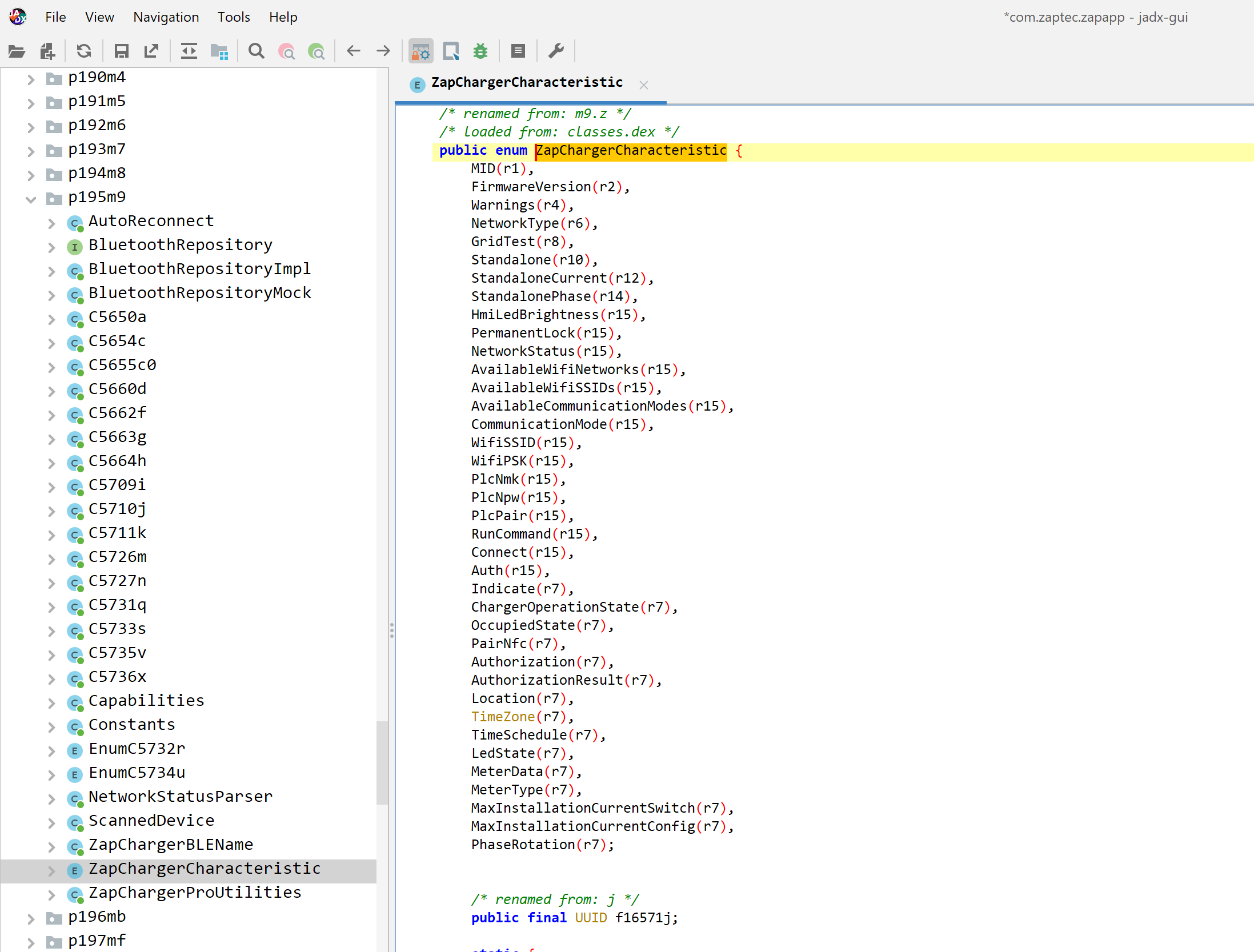
That still begs the question of what can you actually do if you know a PIN code. Before purchasing the charger, we decompiled the Android application and poked around at the Bluetooth Low Energy (BLE) functionality. In the Android application’s list of BLE characteristics the “RunCommand” was certainly interesting.
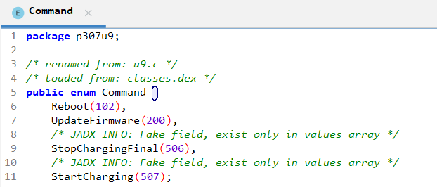
Digging a bit further in the Android application’s code revealed commands to start and stop charging via Bluetooth. Assuming you had the PIN code, maybe you could get free charging by issuing these commands over Bluetooth?
Now with access to the charger’s code we could see what it actually does. The BLE interface was written in Python, which made things easy to look through.
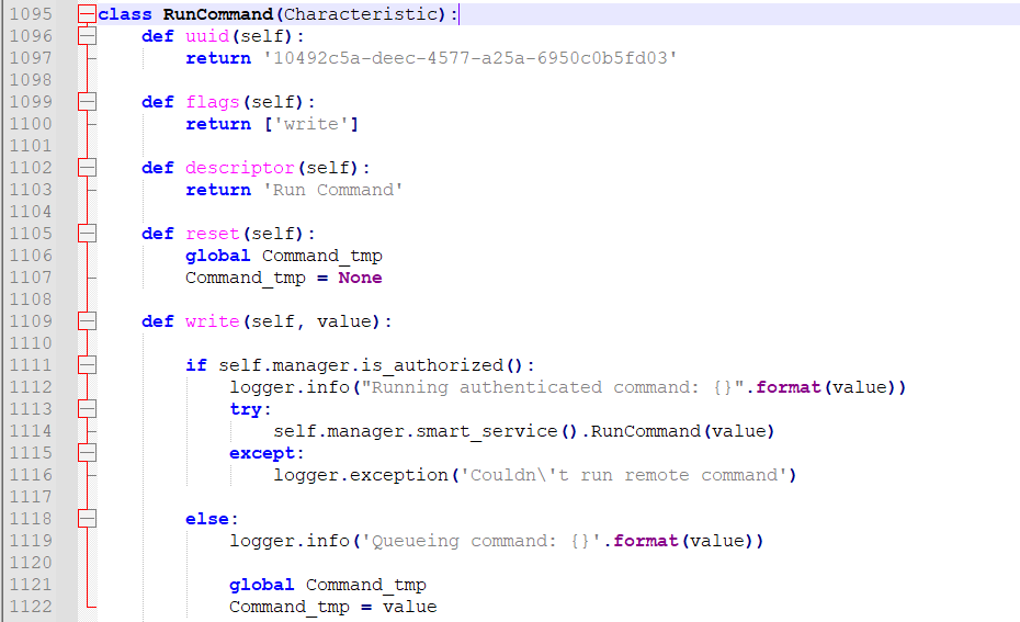
So essentially what happens here is the value of whatever you send to the BLE characteristic gets passed to the smart_service.RunCommand() function. The smart service is another process running on the charger written in .NET mono. Python communicates the smart service through a D-Bus messaging interface. Let’s go see what the RunCommand function can do.
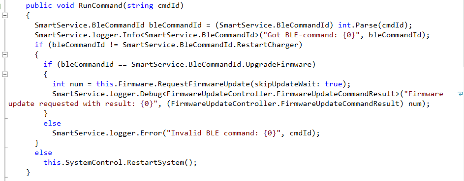
The .NET code only seems to implement the Reboot and UpdateFirmware commands. The StartCharging and StopChargingFinal commands look to be functions that were partially implemented in the Android application, but never implemented on the charger. No free charging via Bluetooth.
So apart from reconfiguring the device, and potentially causing it to disconnect from the network and stop working, what you can do via the Bluetooth interface seems to limited.
It is worth noting that due to the nature of BLE, it would be possible to sniff the PIN code when the device is configured by a technician, but this would require somebody to be listening at that exact moment in time. Zaptec also implemented PIN brute force protection in the Python code. If you enter an incorrect PIN code too many times the Bluetooth interface switches off. The amount of time the Bluetooth interface remains off increases with each incorrect PIN attempt. So, you could brute force the PIN but it would take a long time. And at face value access to the BLE interface for an attacker doesn’t seem to be terribly interesting.
The SSH listener
One of the first things we wanted to do after connecting the device to a network was figure out if there was a hardcoded root password. There wasn’t.
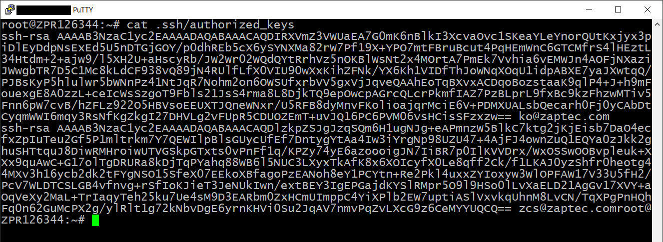
Zaptec placed two public SSH keys on the charger, but the shadow file was empty until we configured a password ourselves in single user mode. This configuration allows Zaptec to login via SSH with the correct key pair, but effectively disables password authentication for both the SSH listener and the UART console.
The Cloud connectivity
The final area we wanted to investigate was the cloud connectivity. We took a few packet captures early on and knew that the charger was talking to the Azure IoT Hub, but couldn’t see what it was sending because the traffic was encrypted.
With root access we were able to install our own root certificate and perform TLS decryption by proxying traffic through mitmproxy.
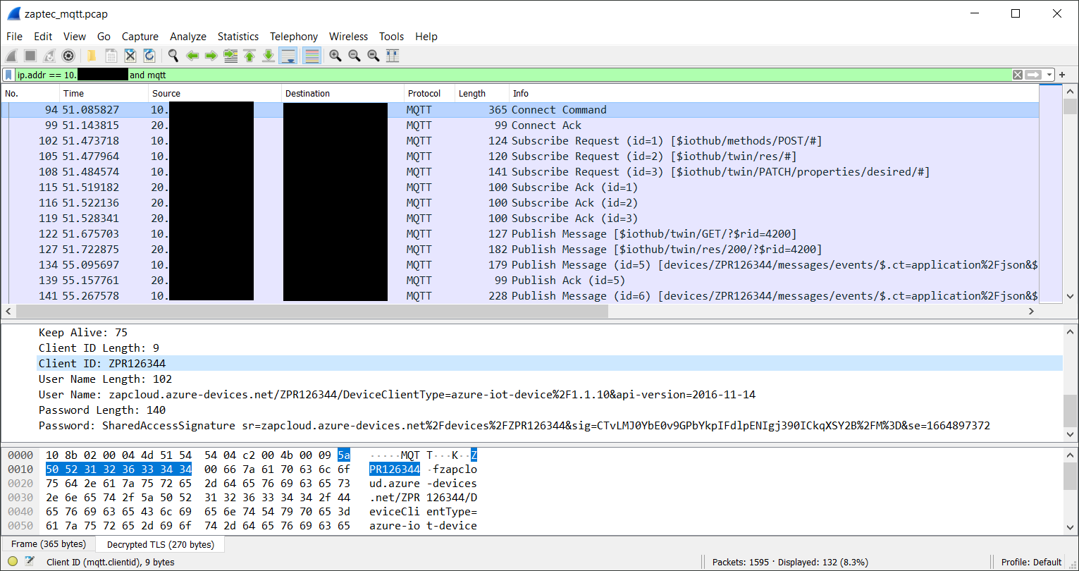
Analyzing a decrypted PCAP allowed us to verify that the charger was communicating with the Azure IoT Hub using Shared Access Signatures, an authentication mechanism that derives credentials based on a secret that was provisioned at the factory.
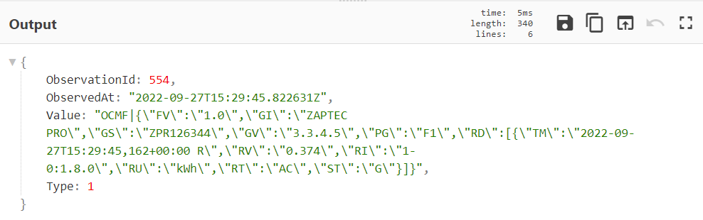
Looking at a few messages published to the IoT Hub revealed the types of data it sends back to Zaptec. A quick look revealed a few things like Linux kernel logs and electricity consumption data.
We also took at a look at the .NET code to see everything it was capable of doing via the IoT Hub. We weren’t able to easily test if this functionality worked, but we did find what appears to be Zaptec’s means of remotely debugging their devices.
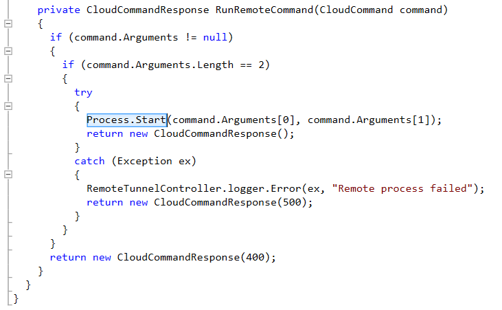
The first is a function called RunRemoteCommand. This passes the contents of a message received from the cloud directly to Process.Start.
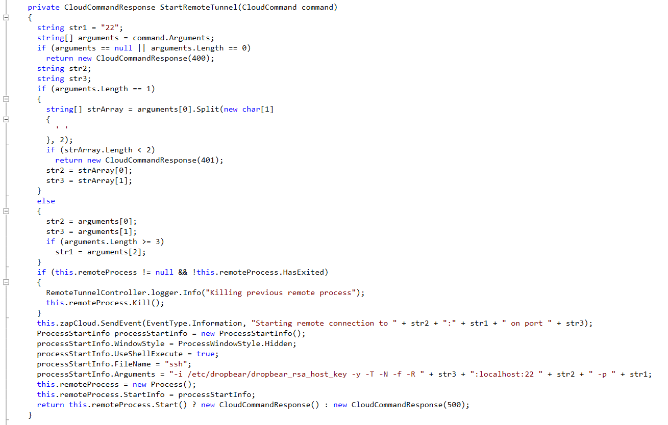
A second interesting function called StartRemoteTunnel appears to allow Zaptec to create a reverse shell back to an SSH listener on the internet.
Conclusion
All in all, we didn’t find any critical security issues during our investigation. Though there is probably room for improvement in a few areas. For example, we would have had a much harder time getting root access to the device if they had used signed firmware, or encrypted the NAND flash. Both of these features are supported by the ARM processor already built into the charger.
Security appears to have been considered at multiple steps along the way, and was better than we expected going into the project.
Get in touch
